WaBis
walter.bislins.ch
How Airplanes follow the Curvature of the Earth, Physics Simulation

Airplane Simulator
Move the sliders and observe how the airplane always finds a new equilibrium altitude. When Pitch Damping is disabled, move the sliders slowly to prevent oscillations. Speed up the simulation up to 100 times using the Time x slider. Change the radius of the earth to observe that the airplane automatically follows the curvature of the earth, no matter its size. Set EarthRadius = 100,000% to simulate a flat earth. Click Reset Pos to move the coordinate system to the airplanes position so the airplane is horizontal again.
- Controls
- Initial Values
- Reset Time
- Reset Pos
- Reset All
- Stop
Stop the simulation by clicking the Stop button, enter the initial values in the input fields and click Reset All to copy the initial values into the simulation. The simulator calculates all the forces due to this initial values, so you can see wheter they yield in stable states or not. If satisfied with the values, click Run.
Physics Simulation

I did not tell the simulation how it has to react to user input and environmental conditions. In real life all systems follow basic physical laws, like Newtons laws of motion. I programmed some simple models of the atmosphere, the earth and the engines, the physical laws and the connections between the different physical systems into the simulator and let it calculate how all aircraft states evolve under this laws. That means this simulation acts like a real airplane that obeys the same physical laws.
Detailed descriptions of the models used, further informations and the source code can be found here:
- Aircraft Simulation Model Explained
- Model of the Standard Atmosphere
- Airplane Lift and Drag Coefficients for the whole Range of AoA
- Turbo Fan Engine Model
- Air Speeds Calculator (
 Calculators and Units Converters)
 - Eine Fluggeschwindigkeit, verschiedene Anzeigen (explanation of air speeds)
- Fluggeschwindigkeiten, IAS, TAS, EAS, CAS, Mach (conversion between air speeds)
- Aircraft Simulation Source Code
This model simulates the whole range for the Angle of Attack and takes air density and compressibility on thrust calculations into account.
Simulation Graphics

Note: the forces in the airplane X axis, i.e. drag and thrust, can be scaled up by a factor of 5, because they are way smaller than lift and weight, see option Fx × 5.
Primary Flight Display

Pitch Damping

This simulator has a Pitch Damping function implemented. The Pitch Damping does not change the altitude the airplane seeks due to trim and engine settings. It only dampens the Pitch and Phugoid oscillations.
Pitch Damping works by enabling an additional negative feedback loop from the output of the first integrator, which is part of the equations of motion and converts accelerations into veloctities, back to its input, see graphic at How a Phugoid works. It uses the pitch rate and the vertical speed to modulate the elevator deflection. I.e. it adds an additional deflection angle to the commanded elevator setting, depending on the actual pitch rate and vertical speed.
We can observe the feedback loop at work. The magenta arrow of the ELEV display shows the commanded elevator angle, while the green arrow shows the elevator angle the airplane effectively sets to prevent oscillations. The green vertical line shows the deflection correction caused by the pitch rate alone. Because this feedback loop causes mostly only very small elevator deflections, it is amplified and displayed as the green line. The difference between commanded and executed elevator angle is due to the whole damping feedback loop, which includes feedback from pitch rate plus vertical speed.
Taking the Curvature of the Earth into Account
Often calculations and simulations treat the earth as flat to simplify equations and calculations. My simulation does not make this simplification. It simulates what happens on a globe earth. This means that the gravity vector changes direction to always point to the center of the earth, as the airplane moves forward. And the simulated atmosphere builds a layer around the earth with a density gradient perpendicular to the surface everywhere like in reality.
The simulation allows to change the radius of the earth. Entering a very big number like 100,000% creates essentially a flat earth. The default value is 5% of the size of the real earth to make the effect of curvature much stronger, so it easier to study. In any case the airplane behaves the same. It flies to the trimmed altitude and stays there, following the surface of the earth, no matter how big or flat the earth is.
Note that the acceleration in equilibrium is not zero, but is a certain value pointing towards the center of the earth. This is the centripetal acceleration that emerges from the simulation that is necessary to keep the airplane following the curvature of the earth. This acceleration is not programmed into the system. It results from the physics naturally, correctly predicted by the simulation. The smaller the radius of the earth is chosen, the stronger the centripetal acceleration is. The passanger don't feel the centripetal acceleration, but they feel a little bit less weight due to the corresponding centrifugal acceleration. This change in the felt G-Force is calculated and displayed on the G-Force Display.
Pressure Altitude
Airplanes measure their Altitude by measuring the static air pressure outside the airplane. Because the air pressure decreases predictably with altitude, the air pressure is used as the input for the altimeters. The measured pressure is converted into an altitude reading and displayed on the Altimeter in feets. Changes in altitude are derived from changes in the measured air pressure or from vertical accelerometers of the Inertial Reference Unit (IRU) and displayed on the Vertical Speed Indicator in feets per minute.

Below the Transition Altitude (e.g. 18,000 ft in the United States and Canada) the pilots have to enter the pressure of local sea level, so called QNH Altimeter setting, so the altimeter shows the elevation above sea level, no matter what the air pressure at that location currently is. They get the QNH from Air Traffic Control (ATC), Tower or ATIS.
Above the Transition Altitude all airplanes set Standard QNH 1013.25 hPa or 29.92 inHg. That means, the airplane constantly climbs and descends when the air pressure outside changes to keep on the programmed Pressure Altitude. Because all airplanes do that, it is guaranteed, that the vertical separation between airplanes is maintained. This way pilots don't have to constantly adjust the altimeter at cruise flight.
You can simulate the behavior of changing local air pressure with the slider ΔP. You can observe that the Altitude on the Altimeter changes as the local air pressure changes and the airplane claims or descends automatically to get back to the trimmed pressure altitude.
How Airplanes follow the Curvature of the Earth
When pilots or the Flight Management Systems commands the airplane to hold a certain altitude, the Autopilot and Fly-by-wire system make constantly adjustments in the Elevator Trim and Thrust setting to hold the commanded Pressure Altitude and Air Speeds. This is the way airplanes hold a certain pressure altitude and speed in reality and by this mechanism airplanes follow the curvature of the earth without intervention of the pilots.
But even when disengaging the Autopilot and the Fly-by-wire system, airplanes are designed in such a way that they naturally hold the pressure altitude they are trimmed for. The interactive physics simulation on this page shows how that works by displaying all forces and the velocity and acceleration vectors.
When the airplane changes altitude or when the vertical component of the wind speed changes, aerodynamic forces acting on the horizontal stabilizer at the tail of the arcraft emerge that create moments that pitch the airplane back into the wind direction. This gives the airplane natural stability. [1] [2] See also Aerodynamic Moments (Aircraft Simulation Model Explained).
Phugoid
A Phugoid is an aircraft motion in which the vehicle pitches up and climbs, and then pitches down and descends, accompanied by speeding up and slowing down as it goes "downhill" and "uphill". This is one of the basic flight dynamics modes of an aircraft, and is a classic example of a negative feedback system. [3]
This oscillation is normally prevented by the autopilot system. In this simulation any pitch oscillation can be damped by enabling Pitch Damping. By disabling Pitch Damping the Phugoid can be observed and studied. If the autopilot of an aircraft is turned off and it has no active fligh-by-wire system and the pilot does not make any control inputs, it will follow the Phugoid oscillation.
 Phugoid phases
Fig. 1 (climbing): An increase in the Elevator Trim angle caused an upward pitch and hence an increase in the angle of attack and hence an increase in the lift force which causes the aircraft to climb. While climbing, the air density decreases and the airplane looses speed and hence the lift force decreases until it gets smaller than the weight. The speed decreases because kinetic energy is converted into potential energy like when a cart drives uphill.
Fig. 2 (top): The lift force is now smaller than the weight, so the airplane stops climbing and starts to pitch down.
Fig. 3 (descending): The airplane descends, the air density increases and the speed increases and hence the lift force increases until it gets bigger then the weight. Then the airplane stops descending.
Fig. 4 (bottom): The airplane has stopped its descend because the lift force is now bigger than the weight. The airplane has reached its lowest altitude of the Phugoid and starts to climb again. The whole cycle repeats a few times.
One oscillation takes about one to two minutes. The maximum and minimum altitude of the Phugoid oscillation slowly approach a mean altitude inbetween, the new Equilibrium Pressure Altitude for the current Elevator Trim and Thrust setting.
The aircraft pitches always towards the direction of the flight path (green arrow), keeping the angle of attack constant. The angle of attack depends on the Elevator Trim setting and the position of the Center of Gravity (CG).
Pilots do not have to dip the nose to follow the curvature of the earth. Airplanes are designed to do so automatically, even without pilot or autopilot intervention.
How a Phugoid works
The Phugoid is a damped oscillation. We can study the control loop diagram of a simple damped harmonic oscillator, like a 1-dimensional mass-spring system, and look for similarities with the airplane control loop diagram. Although the control loops of the simulation (and the real airplane) are much more complicated and not only 1-dimensional, see Aircraft Simulation Model Explained, there are some commonalities:
They both have 2 stages of integrators Int(x), from acceleration Accel to velocity Veloc, from velocity to position X/Alt, and 2 negative feedback loops, one from velocity Veloc back to the input of the first integrator, and one from the position X/Alt back to the first integrator. The outer loop is responsible for the oscillation, the inner loop for the damping of the oscillation. This can be derived by finding the differential equation for the system and solve it, which is beyond the scope of this page.

Although the lower diagramm shows only a very simplified version of the aircraft control loops, where I even combined 2 dimensions (x,z) into 1 dimension (z), I can still explain how the Phugoid works in prinziple with this model.
As the altitude increases, the lift force decreases and as the altitude decreases, the lift force increases, because the lift force depends on the density of the air, which depends on the altitude. This negative outer feedback causes the vertical oscillation of the Phugoid, like the oscillation of the mass-spring system. On the other hand, as the the speed increases, the produced thrust of the engine decreases and vice versa. This negative inner feedback loop damps the Phugoid oscillation.
In the simulation we can observe the Phugoid oscillation and how the acceleration vector rotates around the airplane, which is a 2-dimensional coupled oscillation due to the complicated interplay of the airplane forces and systems. The acceleration vector rotates because the X and Z components are 90° out of phase, because the X component only passes through one integrator (inner feedback loop), while the Z component passes through two integrators (outer feedback loop). Each integrator shifts the oscillation sine phase 90°.
Coffin Corner
 PFD of Airplane in the Coffin Corner
There are some other limits that prevent airplanes from flying above a certain ceiling altitude.
- Structural stresses due to overspeed
- Detachment of the airflow above the wing due to local airflow near or above the speed of sound causing loss of lift
- Minimum speed to create enough lift to counter the weight
- Minimum speed to be able to maneuver without stalling
- Maximum angle of attack to create lift and not to stall
The higher the airplane flies, the less dense the air is. To create the needed amount of lift, the airplane has to travel much faster through the less dense air in higher altitudes. But this means that at some altitude it approaches the speed of sound, which even decreases with increasing altitude. So the speed of sound puts an upper limit the airplane is able to fly. The airplane in the simulation is limited to Mach 0.82. If the speed gets higher, it would loose lift and stall (stall is not implemented in the simulation).
The Mach limit decreases with altitude because the air density and temperature decrease with altitude. The Mach limit can approach the minimum Calibrated Air Speed (CAS) needed to be able to maneuver and not to stall.
So at very high altitudes, the airplane can't go faster and can't go slower to not to stall. This region is called Coffin Corner. Note, that not the engine power is the limiting factor.
You can simulate a Coffin Corner by setting the following parameters in the simulation: Trim = 81%, Thrust = 97%, Mass = 56.5t. Increase the Trim angle only step by step. In this case the margin to the speed limits is almost nonexistent. You are in a Corner where you can't maneuver anymore.
The speed limits depend on the weight of the aircraft. The limits are displayed on the Speed Tape as red bars. The upper bar shows the maximum CAS allowed to operate withing the stress limits or the maximum CAS for the Mach limit, whichever is smaller. The lower filled bar shows the minimum CAS for not to stall and the red border bar shows the minimum maneuvering speed, the speed to be able to make turns without stalling.
The image of the Primary Flight Display (PFD) on the right shows how flying in the Coffin Corner looks like to a pilot.
G-Force Display
The G meter in the lower right portion of the PFD shows values less than 1 in equilibrium flight due to the centrifugal acceleration upwards, away from the center of the earth, caused by following a downward curved earth surface.
Some airplanes have a G-Force Display that shows a value less than 1 in reality, which proves the airplane follows the curvature of the earth. Depending on east or west direction of flight this value is different due to earths rotation, exactly as predicted by the globe model. See Centrifugal and Gravitational Acceleration in an Aircraft for an experiment executed by the pilot Wolfie6020.
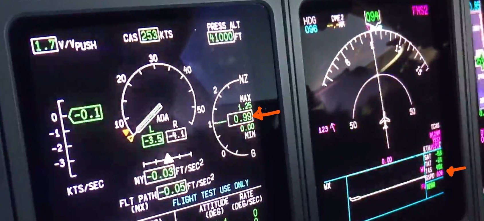
 G-Force Display from a Bombardier Global Express Cockpit in level flight, Value grel = 0.99
In the simulation this value depends on the chosen size of the earth. The smaller the earth, the stronger the curvature, the smaller the G value. If you set the radius of the earth very big (100,000%), then the curvature is almost zero and the display shows G 1.00. See G-Force Meter for how the G-Force is calculated.
Note: The centrifugal acceleration and the associated G value are not programmed into the simulator. They naturally emerge from the programmed physical laws.
References
Pitch stability means when the nose pitches up, the aerodynamics make the nose go back down. We'll take a look at how to arrange the wing and tail to make this happen.
https://www.youtube.com/watch?v=1bQT9YUvtkw&t=11s
Chapter 7: Introduction to Aircraft Stability and Control
https://research.iaun.ac.ir/pd/ekianpour/pdfs/UploadFile_9029.pdf
The Airplane was drawn by Walter Bislin using Inkscape, stored in SVG format and then converted to graphic calls used by this App with SVG to Jsg. Download:  A320 sideview filled blank.zip .