WaBis
walter.bislins.ch
Rainy Lake Experiment: Equipment
The Rainy Lake Experiment used a variety of tools. Some of them are listed and explained here.

Theodolite and Auto Level
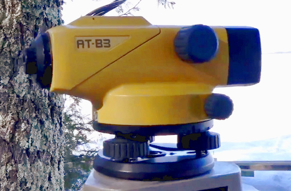 Img 1: Auto level TOPCON AT-B3
 Img 2: Theodolite Wild T2 (mod): 1973 - 1996
Image 1: The Auto level TOPCON AT-B3 was the main equipment used by George Hnatiuk. [1] It's sole purpose is to establish a tangent level to the earth where it is mounted. If you look through the scope, as an object in the distance is on the horizontal crosshair, it is on the extended tangent line of the auto level, also called eye level. The auto level does not measure vertical angles nor distances. That is the domain of theodolites.

The TOPCON auto level has a 28x zoom and the specifications state an accuracy of 0.31" (0.31 arcseconds = 1.5 mm at 1 km distance). Compensator setting accuracy is 0.5". The measured accuracy is within 7" (see Calibration of the Auto Levels), which gives an uncertainty in height at the last Tangent target (7) at 9.5 km distance of 0.32 m. For comparison: the vertical size of the Target (7) is 1.6 m.
Image 2: The Theodolite Wild T2 (mod): 1973 - 1996 has a zoom of 30x and a reading accuracy of 1". The accuracy of the theodolite at the Tangent target (7) is 0.05 m.
 Img 4: Theodolite TOPCON Total Station GTS-3C
 Img 5: Auto level CST/berger SAL 20
 Img 3: Scope TOPCON Total Station
Image 4: The Theodolite TOPCON Total Station GTS-3C provides electronic angle reading and distance measuring functions. Angle reading is provided with 10" accuracy and distance measurement is provided up to 1.8 km. The station measures horizontal and vertical angles, slope distances, horizontal distances, relative elevation, coordinates of an unknown point and elevation. The accuracy of the theodolite at the last Tangent target (7) is 0.46 m.
Image 3 shows how the accuracy of the TOPCON theodolite looks like if you look through it. The Tangent target (7) is, barely visible, a tic above the right horizontal crossbar. The vertical size of the target plate is 1.6 m.
Image 5: The Auto Level SAL 20 features a penta prism for even bubble viewing and a top-mounted peep sight. Leveling accuracy is 22" (1/8 of an inch at 100 feet). The accuracy of the auto level at the last Tangent target (7) is 1.0 m. For comparison, the apparent lift due to refraction at this distance for standard refraction k = 0.17 is 1.2 m.
Calibration of the Auto Levels
 Img 6: Hall for calibrating the auto levels
At each end of the 146.6 m long hallway there is a target mounted at a specific height. The target has two horizontal lines with a gap of 1/100 of an inch used for sighting. You sight the targets from both ends of the hallway. Then you adjust the compensator of the auto level so that both lines appear exactly at the center of the horizontal crosshair. George measured an accuracy of better than 7". [2]
Corner Reflector
 Img 7: Corner Reflector
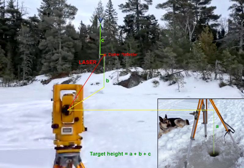 Img 8: Measuring Target height
Image 7: A Corner Reflector is a Retroreflector consisting of three mutually perpendicular, intersecting flat surfaces, which reflects waves back directly towards the source, but translated. The three intersecting surfaces often have square shapes. Optical corner reflectors, called corner cubes, made of three-sided glass prisms, are used in surveying and laser ranging. [4]
Image 8: You mount the Corner Reflector beside the target you want to measure. You place a theodolite capable of measuring distances using a laser, at an exactly known position and elevation and aim at the Corner Reflector. The theodolite gives you exact angles, slope distance, horizontal distance and relative elevation to the reflector. Heights a and c are measured with a tape and height b is the relative elevation as calculated by the theodolite. [5]
The height of the Tangent target (7) was first measured with the TOPCON Total Station at a near point on the ice and the reflector at the target as shown in image 8. Later the exact GPS Vector of the center of the target was measured by Jesse Kozlowski using Differential GPS Equipment.
Differential GPS Equipment
 Img 9: Jesse using Trimble GNSS System
The Differential GPS equipment consists of at least one fixed GNSS receiver working as a Base Station, one mobile GNSS receiver, connected to the Base Station, for measuring different locations, and a Controller to control the GNSS receivers. The GNSS receivers use Global Navigation Satellite Systems (GNSS) like Navstar and GLONASS to calculate GPS Vectors to the locations of the GNSS receivers. [7]
Each location is measured multiple times to get a statistical probability for the accuracy of the measurements. The Base Station provides error corrections to the mobile receiver to enhance the accuracy of the measurements by factors. Post-processing the GPS vectors using software on a computer and the Continuously Operating Reference Station (CORS) the measurements can be further enhanced to cm accuracy. See Improving GPS accuracy with Differential GPS.
The following Differential GPS equipment was used in the Rainy Lake Experiment:
- Trimble R10 GNSS System receiver working as the Base Station
- Trimble R10 GNSS System receiver working as the mobile station
- Trimbel TSC3 Controller to control the GNSS receivers
Trimble R10 GNSS System
The Trimble R10 GNSS system, together with the Trimble Access field software and the Trimble Business Center office software, provides the most advanced GNSS surveying system on the market. [8]
- Powerful 440-channel solution with Trimble 360 technology delivers the most advanced satellite tracking.
- Trimble CenterPoint RTX delivers GNSS corrections via satellite or internet connection anywhere in the world for unprecedented speed and accuracy for a PPP solution.
- Pair with Trimbel TSC3 Controller, Trimble Tablet, Slate or Trimble CU for the most powerful solution on the market.
The Trimble R10 GNSS receiver incorporates a GNSS antenna, receiver, internal radio, and battery in a rugged light-weight unit that is ideally suited as an all-on-the-pole RTK rover or quick setup/rapid mobilization base station. LEDs enable you to monitor satellite tracking, radio reception, data logging status, Wi-Fi status, and power. Bluetooth wireless technology provides cable-free communications between the receiver and controller.
You can use the receiver as part of an RTK GNSS system with the Trimble Access software. The receiver can optionally record GNSS data to the receivers internal memory and download to a computer or USB flash memory stick.
Real-Time Kinematic (RTK) operation provides centimeter-level precision by eliminating errors that are present in the GNSS system. For all RTK operations, you require both a rover receiver and a source of corrections from a base station or network of base stations.
A base station consists of a receiver that is placed at a known (and fixed) position. The receiver tracks the same satellites that are being tracked by the rover receiver, at the same time that the rover is tracking them. Errors in the GNSS system are monitored at the fixed (and known) base station, and a series of position corrections are computed. The messages are sent through a radio link to the rover receiver, where they are used to correct the real time positions of the rover.
The rover receiver is moved between the points that require measurement or stakeout. The rover receiver is connected to a base station or to a source of RTK corrections such as a VRS system or the Trimble CenterPoint RTX correction service. The connection is provided by:
- an integrated radio
- an integrated cellular modem
- an integrated Wi-Fi module
- a cellular modem in the controller
- an integrated GNSS antenna (L-Band)
Trimbel TSC3 Controller
The Trimble® TSC3 controller with Trimble Access software is a handheld field computing solution that streamlines the flow of everyday surveying work and the number of devices you need in the field. [9]
- Bluetooth wireless technology eliminates cables
- Wireless internet connectivity with integrated GSM/GPRS modem
- Compatible with all Trimble GNSS positioning systems incl. Trimble R10 GNSS System
- Receive of GNSS Base Station correction signals
- The integrated 3G-Model provides access to the internet to receive Base Station correction signals and to provide data synchronisation
Differential Correction
Differential correction is the process of correcting GNSS data collected on a mobile GNSS receiver (rover) with data collected simultaneously at a base station. Because the base station is on a known location, any errors in data collected at the base station can be measured, and the necessary corrections applied to the rover data. See Improving GPS accuracy with Differential GPS.
Differential correction can be done in real-time, or after the data is collected by post-processing.
Magellan SporTrak Pro
 Img 10: Magellan SportTrak Pro GPS receiver
SporTrak Pro can track up to 12 satellites at any one time out of the current constellation, and fully supports WAAS (Wide Area Augmentation System) in the US and EGNOS in Europe. With current GPS accuracy, the SporTrak Pro will be accurate within 3 meters or better depending on line of sight to the satellites and the amount of strong satellite signals the receiver has [10].
The Magellan SporTrak Pro was used to roughly measure the positions of the targets. Much more accurate measurements were taken later by using Differential GPS Equipment.
Lantern
 Img 11: Lantern used for the Night Observations
This lantern were used to make the Night Observations.
Poles for Targets
 Poles for Targets
This sewer pipes were used as the poles for the Targets that were planted on the ice.
Drones
 Img 11: Drone DJI Mavic Pro
Video: Mavic Pro following George and Jesse driving from observer location to target (2) on snow mobile. Drone lost contact and was fighting with the wind. [11]
 Img 12: Drone Voyager 4
Voyager 4 Observation showing horizon drop with altitude and revealing more and more land in the distance previously hidden by the curvature of the earth. [12]
References
The TOPCON auto level was the mainly used instrument by George Hnatiuk
http://www.youtube.com/watch?v=GUO-mbxybVA#t=1169s
Calibration of TOPCON auto level explained by George Hnatiuk
http://www.youtube.com/watch?v=kOqlAir8cdI#t=7426s
How to calibrate an Auto Level
http://www.youtube.com/watch?v=XYsjyMPb-cI#t=85
For a quick explanation on the design and operation of corner reflectors
http://www.youtube.com/watch?v=dsRsap2_RAc
Measuring height of Target (7) using TOPCON theodolite and corner reflector
http://www.youtube.com/watch?v=lL3693c0RxI#t=5274
Jesse asking for a place for the Base Station for Differential GPS
http://www.youtube.com/watch?v=lL3693c0RxI#t=3983
https://www.trimble.com/EC_ReceiverHelp/V4.41/en/SetupGuidelines_BaseStationOpGuidelines.htm
Datasheet, Documentation, R10 Video, Brochures, Support, Downloads
https://www.trimble.com/survey/trimble-r10.aspx
Product Infromation, Support & Download
https://geospatial.trimble.com/products-and-solutions/trimble-tsc3
Footage of drone following George and Jesse driving from observer location to target (2) on snow mobile. Drone lost contact and was fighting with the wind.
http://www.youtube.com/watch?v=kOqlAir8cdI#t=1343
Footage of Voyager 4 drone showing ice horizon drop with altitude
http://www.youtube.com/watch?v=kOqlAir8cdI#t=1996