WaBis
walter.bislins.ch
Rainy Lake Experiment: Targets
The key elements of the Rainy Lake Experiment were the Targets. This page describes the targets, how they are planted and how their GPS Vectors (positions) were measured.
 Img 1: All targets ordered by distance
Image 1: The target dimensions get bigger with increasing distance as described in Calculating Target Size. At the same time the height of the upper Tangent targets increases according to Calculating Tangent Target Heights [1]. The data is listed at Target Positions and Sizes relative to the Observer.
 Img 2: Bedford targets (1), (3) and (5)
 Img 3: Bedford and Tangent targets (2) and (4)
Image 2 and 3: Details of the target plates (1) to (5). Note the dimension shown in the images are the dimensions used in the computer model as listet in the table Target Positions and Sizes relative to the Observer, not the real dimensions. But the difference is small.
Planting the Targets

 Img 4: Using a chain saw to mill a hole into the ice
 Img 5: Rectangular hole for pole
Image 4 and 5: To plant the targets (1) to (6), holes were milled into the 75 cm thick ice using a chain saw or drilled using an ice auger about 50 cm deep [3].
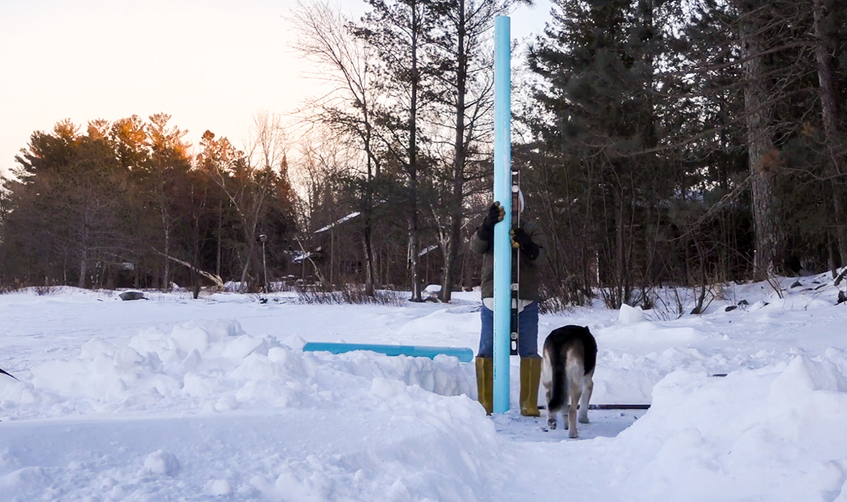 Img 6: Making sure the pole is upright with a spirit level
 Img 7: Fixing the pole with snow, ice and water
Image 6 and 7: The poles were placed in the holes and the space around it filled with snow and water that turned into ice over night.

 Img 9: Targets are adjustable attached with a clamp to the poles
Image 8: It was quite an efford to plant the bigger targets alone [4].
Image 9: The higher targets were mounted on wooden sticks with a clamp so they could easily be adjusted as needed.
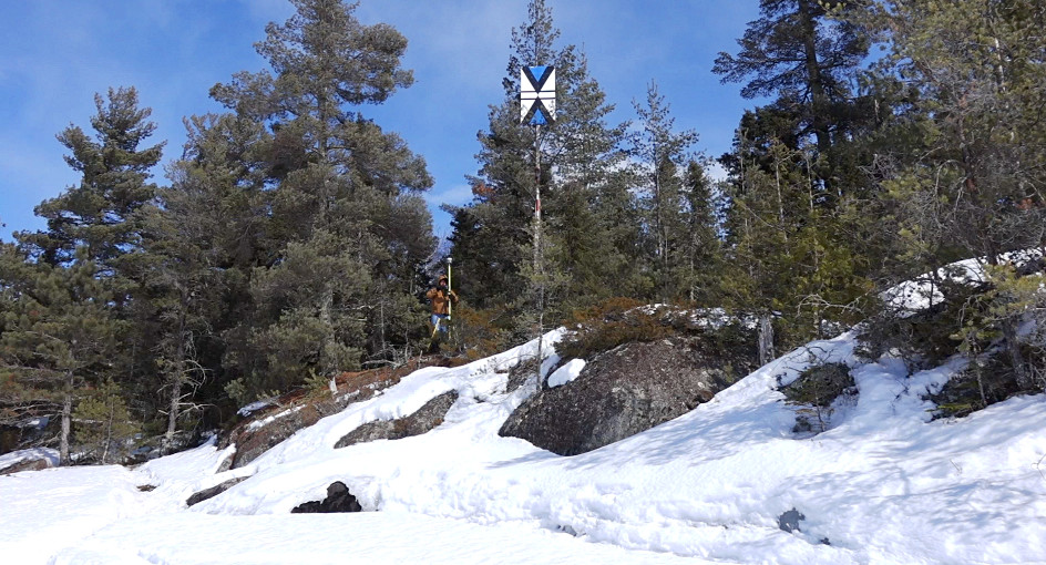
Image 10: The last Tangent target (7) had to be mounted high on a tree on Home Island to be 10.8 m above water level so it appeared at eye level at an observer height of 3.91 m in 9.46 km distance. The target plate size is about 1×1.6 m.
The Bedford targets were all mounted as accurate as possible 1.85 m above water level. The Tangent targets however were not mounted exactly at the pre-calculated heights. George Hnatiuk wanted to align the Tangent targets visually to eye level of the observer. He observed the targets through the auto level at the observer location at times with low refraction, estimated the height deviation from eye level, drove to the target and adjusted it accordingly [5]. Although the Tangent target heights were set visually, their hight is close to the pre-calculated heights, only diverging in the expected range of common low refraction variations.
Because the Tangent targets were adjusted at different times and days, the resulting heights depended now on the refraction of the time the targets were observed and adjusted. This is the reason why the Tangent targets appear not in a consistent height. Apparent Lift due to Refraction can change considerably after some km. But this does not change the outcome of the Experiment.
George states that he has much experience from observations over many months, at what conditions refraction is minimal [6].
 Img 11: Drilling a hole to find water level
 Img 12: The hole fills with water
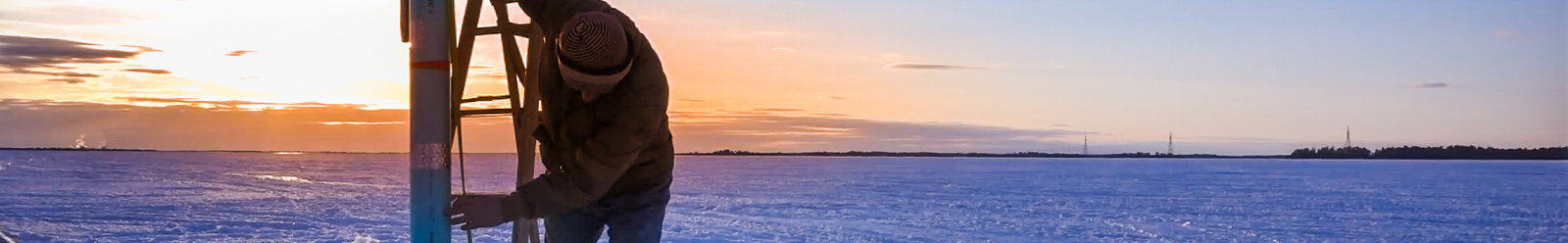
Image 11: To adjust the Bedford target heights and measure the Tangent target heights with respect to the water surface of the lake, a hole was drilled into the ice near each pole using an ice auger, all the way through the 75..85 cm thick ice to the water below.
Image 12: The holes filled with water almost to the top of the ice surface indicating the water level of the lake. A small channel lead the water to the base of the poles from where the height of the target centers was measured using a measuring tape.
- Video: George drilling a hole with the ice auger, almost getting wet feets
- Video: Drone following George and Jesse driving to target (2) on snow mobile
Drone was fighting with the wind and lost contact.
Measuring the Targets
The positions of the targets were measured by Jesse Kozlowski to cm accuracy using his Differential GPS equipment and post-processing of the collected data. The center of the farthest Tangent target (7) was also measured with GPS. All other target center heights were measured by George Hnatiuk using a measuring tape from water and ice level. See Location Graph and Data for all measurement results.
The whole measuring process was as follows:
- George Hnatiuk planted the targets at planed distances from the observer location. He used his Magellan SporTrak Pro GPS receiver to locate their planed positions.
- The Bedford targets were all mounted on the poles at a height of exactly 1.85 m above the water level at the target position using a measuring tape.
- The Tangent targets were mounted by repeated trial and error over many days on low refraction conditions so they appeared finally at about eye level as seen from the observer location at an observer height of 3.91 m. The final target heights above water level were then measured using a measuring tape, except the last target height, which was measured using a theodolite from a nearby location on the ice as shown on the image 8 at Corner Reflector.
- The height of the ice surface above water level at each target was also measured using the measuring tape or ruler.
- Jesse Kozlowski placed his GNSS Base Station on the ice near the observer locations and recorded its position for later post-processing of all measured GPS Vectors. The Base Station is used to calculate an error correction signal for the other mobile GNSS Receiver.
- Jesse Kozlowski measured and recorded the GPS Vectors (3D positions) in ECEF Cartesian (x,y,z) coordinates to the ice beneath each target, except for the last Tangent target (7). The vector to the last Tangent target in the tree was measured by holding the GNSS Receiver up to the target as shown in image 14.
- Each GPS Vector was automatically measured and recorded multiple times in sequence by the mobile GNSS Receiver to be able to calculate and increase the accuracy of the measurement using statistics.
- Later in the office Jesse Kozlowski used GNSS software that uses data from Continuously Operating Reference Station (CORS) to post-process all measurements to further improve the recorded measurements to cm accuracy: horizontal < 2.9 cm, vertical < 5 cm.
- The software also computes latitude, longitude and ellipsoid height of the GPS Vectors and calculates the elevation above the GEOID12B Geoid (mean sea level), see Obtaining Elevations.
- From the post-processed, error corrected GPS Vectors he calculated the vectors to the water levels and target centers using the target and ice heights measured by George.
 Img 13: Base Station sending Corrections to mobile GNSS Receiver
 Img 14: George holding GNSS Receiver to center of target (7)
 Img 15: Measuring GPS Vector to ice at target
 Img 16: Accuracy of Measurement on Trimbel TSC3 Controller
At the end we had a collection of GPS Vectors to the center, ice level and water level of each target with cm accuracy (horizontal < 2.9 cm, vertical < 5 cm). This vectors were transformed to a local coordinate system at the observers location by Walter Bislin for his Computer Model using his WGS84 Calculator. This calculator was also used to confirm the post-processed transformations into Geodetic Ellipsoidal coordinates done by Jesse Kozlowski. See WGS84 Coordinate System for the math involved with this transformations.

 Download Original Data
Videos
- Jesse and George measuring the height of the Tangent target (7)
- Jesse explaining how he measured targets with Differential GPS
- George mounting the GPS receiver at Tangent target (7) in the tree
- George in tree with Jesse reading data from Trimble
- Jesse making measurements with Trimbel TSC3 Controller at a Bedford target
George commenting on the targets
http://www.youtube.com/watch?v=lL3693c0RxI#t=4204
George explaining setup for planed targets on the whiteboard
http://www.youtube.com/watch?v=GUO-mbxybVA#t=485
Drilling a whole with chain saw to plant target (6) and planting of target
http://www.youtube.com/watch?v=lL3693c0RxI#t=5622
George planting tall target (6)
http://www.youtube.com/watch?v=lL3693c0RxI#t=5701
Jesse explains how the tangent targets were set up
http://www.youtube.com/watch?v=kOqlAir8cdI#t=414
George talking about his experience with refraction at the Rainy Lake
http://www.youtube.com/watch?v=kOqlAir8cdI#t=5299